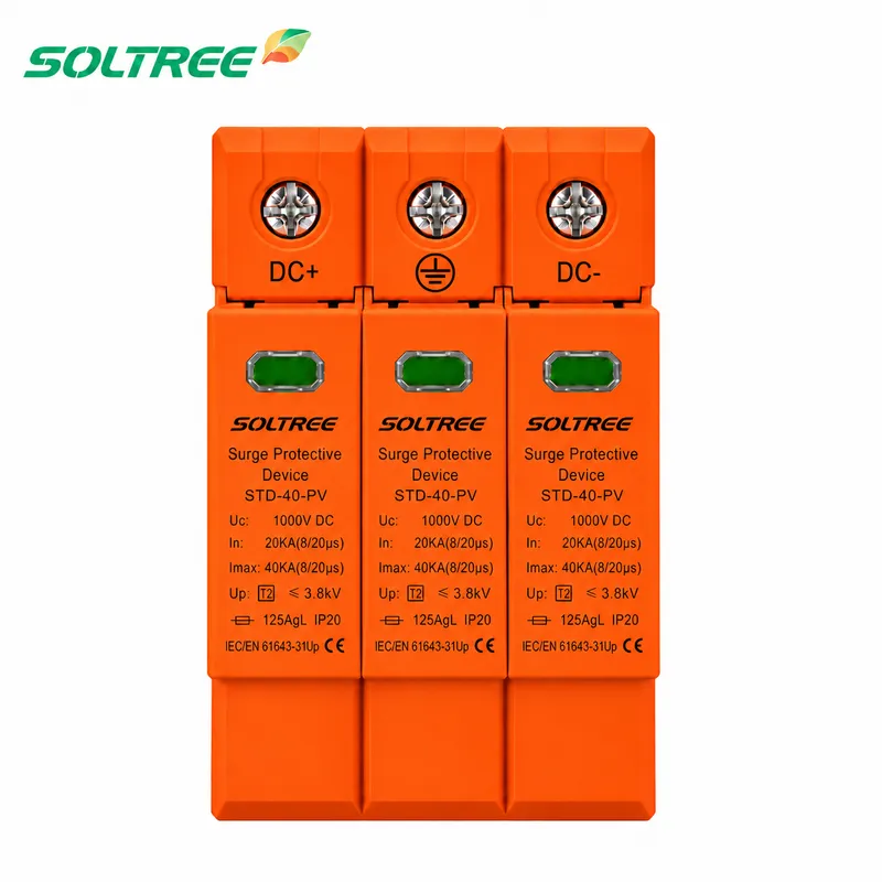
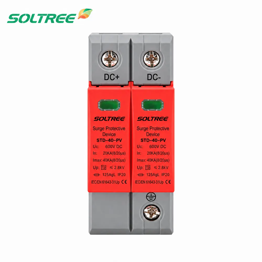
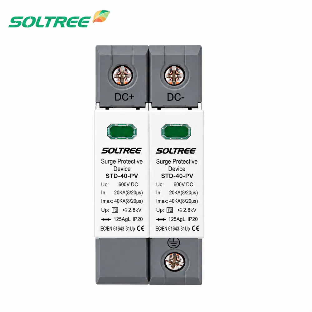
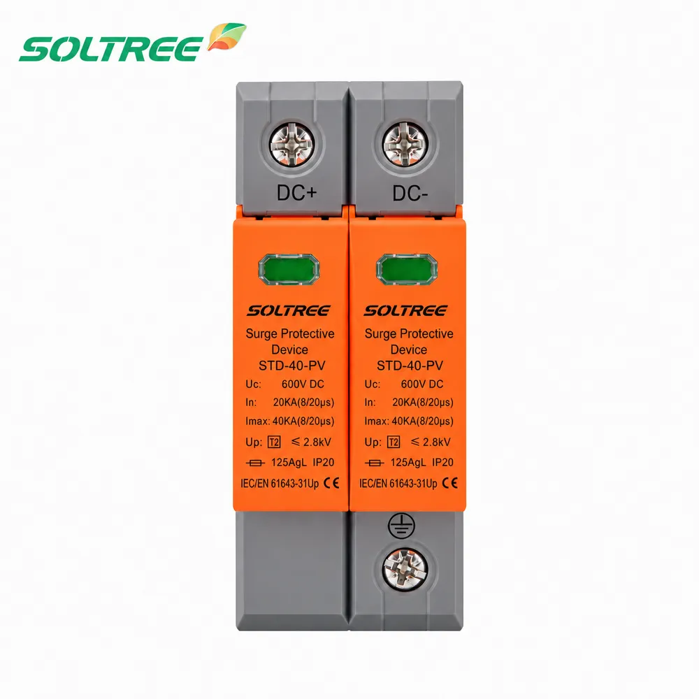
DC Surge Protector
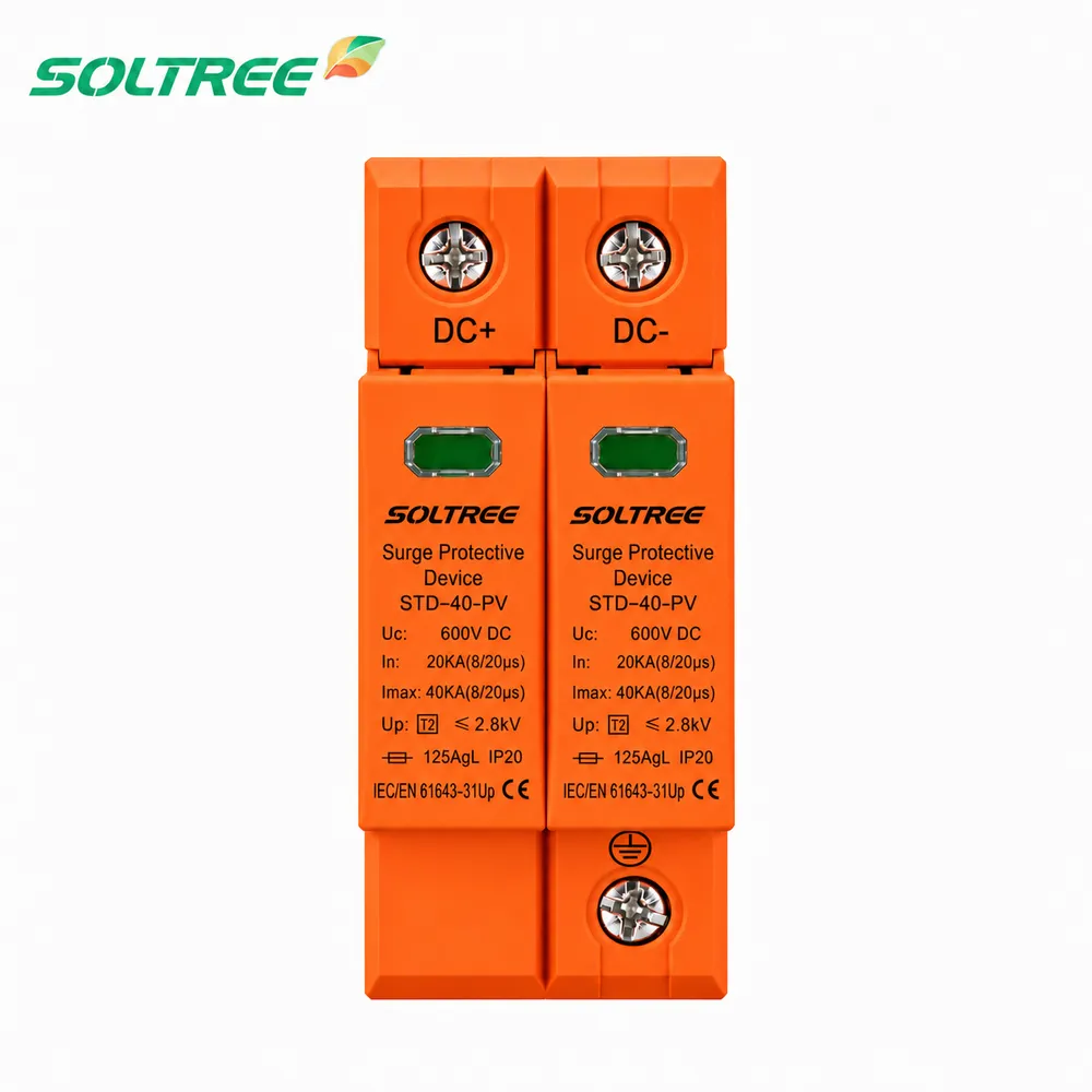
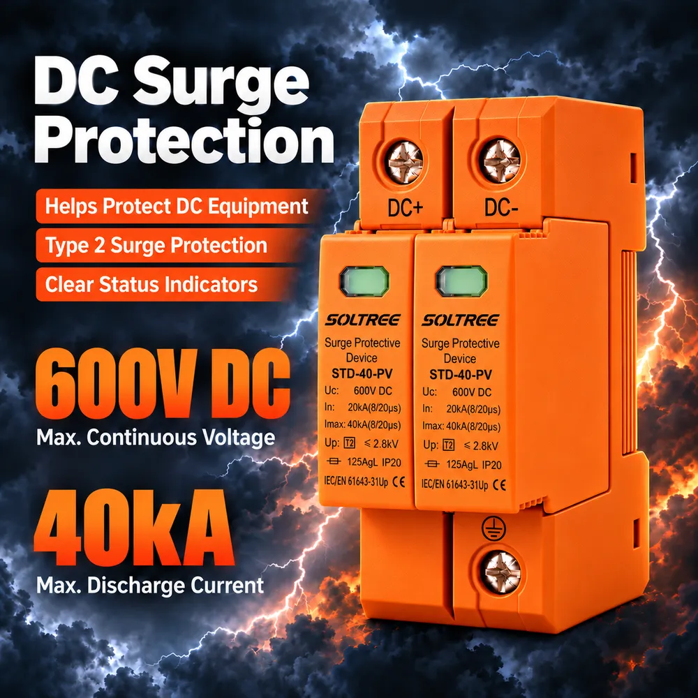
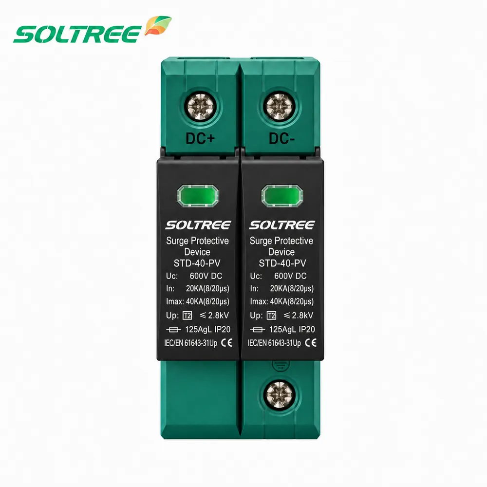
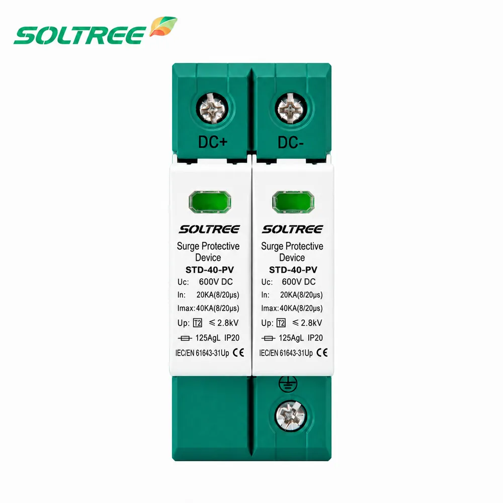
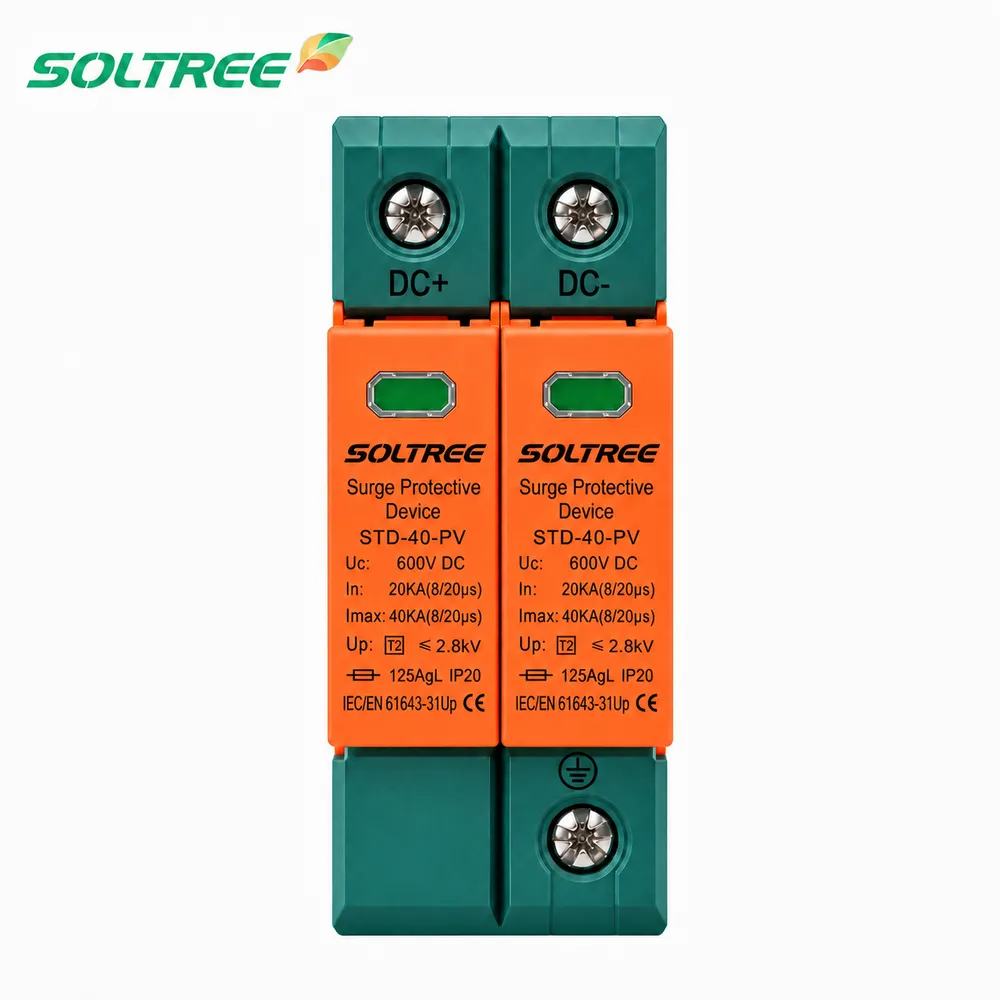
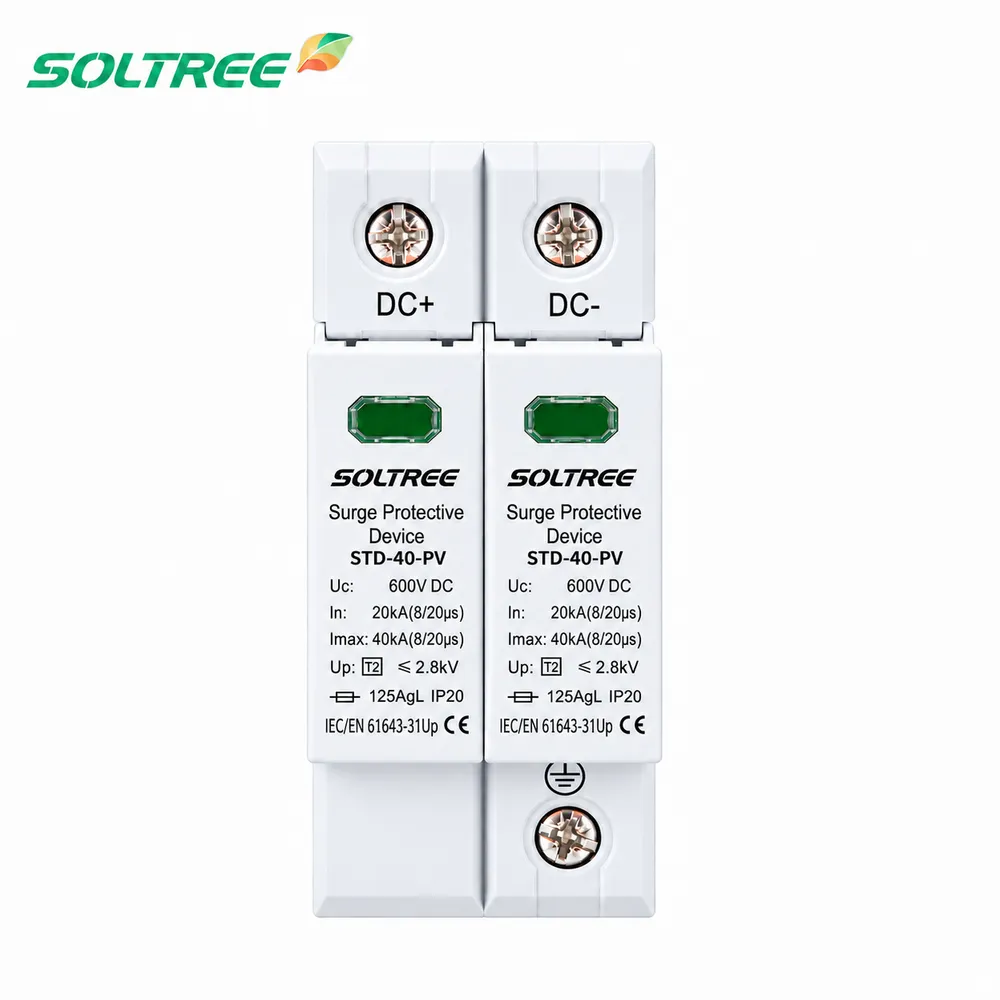
Type 2 600V 2P DC Surge Protector SPD STD-40-PV
DIN rail installation, for 600V DC power system, high discharge capacity due to Metal Oxide Varistor (MOV)
Key Features
- Location of Use: String box, inverter
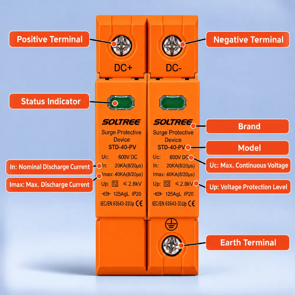
- Network Systems: (DC+)-PE, (DC-)-PE
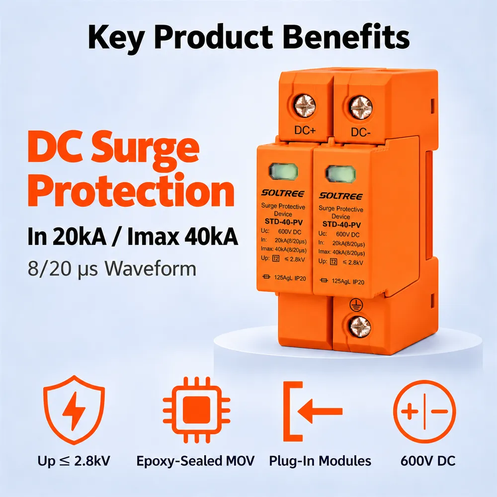
- Surge Ratings: In = 20kA (8/20 μs), Imax = 40kA (8/20 μs)
- IEC/EN Category: Class II / Type 2
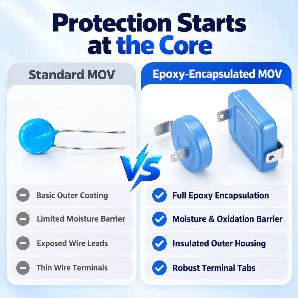
- Protective Elements: High Energy MOV
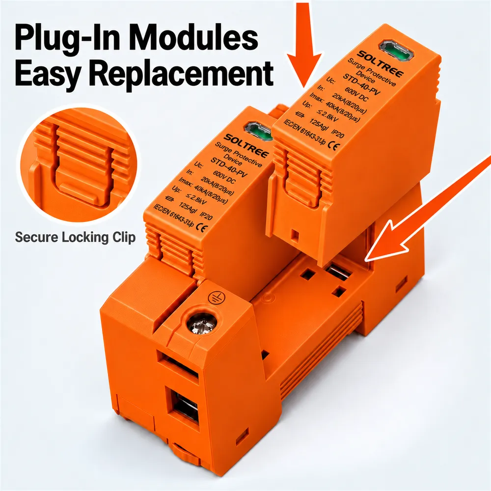
- Housing: Pluggable Design
- Compliance: IEC/EN 61643-31
Samples available · OEM pricing on request · Ships worldwide
Application
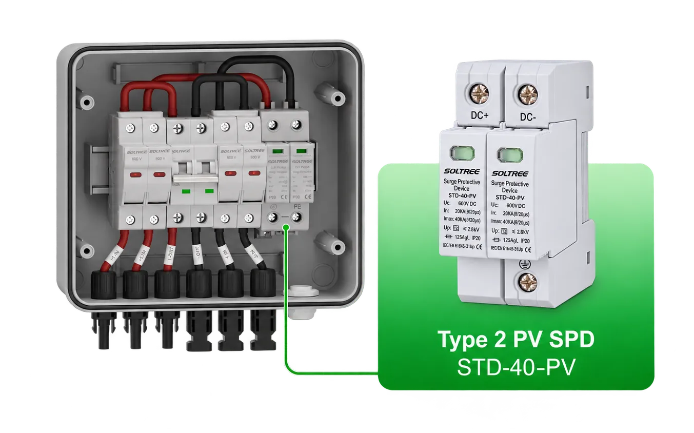
The STD-40-PV is a Type 2, 2-pole 600V DC surge protector for photovoltaic (PV) circuits. Designed for installation in PV string boxes, combiner boxes and at inverter DC inputs, it protects connected equipment against transient overvoltages caused by induced lightning surges.
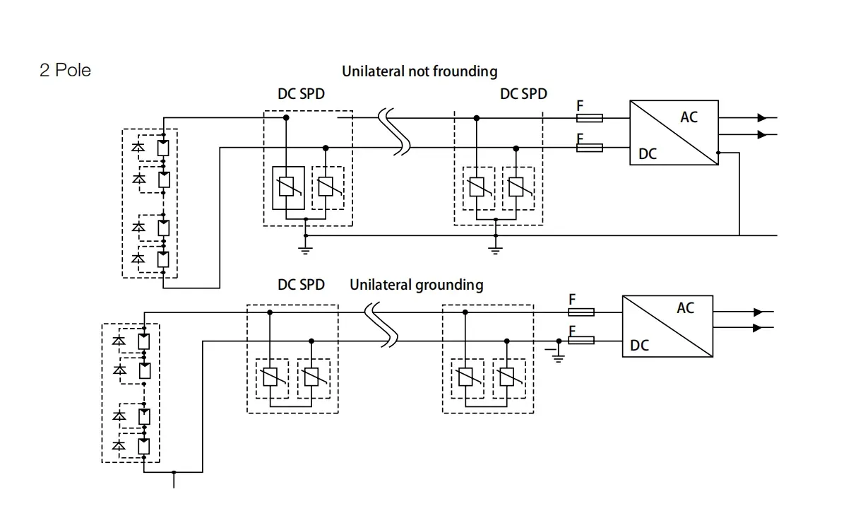
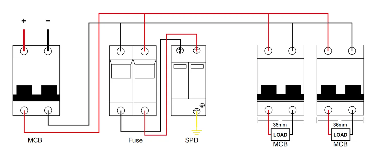
Connect the SPD in parallel with the DC circuit, following the 2-pole wiring diagram for the positive, negative and protective earth connections. For long outdoor DC cable runs, plan protection at both the PV array side and the inverter/converter side, and confirm that the circuit voltage is within the selected SPD rating.
High-energy metal oxide varistors (MOVs), dedicated thermal disconnectors and failure indicators provide surge protection, thermal disconnection and a visible indication of device status.
Specifications
Compare the STD-40-PV 2P DC surge protector ratings below, including 600V and 800V options and a customized 12/24V option. The table lists the Class II test classification, nominal discharge current (In), maximum discharge current (Imax) and voltage protection level (Up) to help you review the configuration for your PV circuit.
| Pole | 2P | 2P | 2P(Customized) |
|---|---|---|---|
| Classified Test | Class II | Class II | Class II |
| Ucpv (VDC) | 600 | 800 | 12/24 |
| In (8/20)μs (kA) | 20 | 20 | 20 |
| Imax (8/20)μs (kA) | 40 | 40 | 40 |
| Up (kV) | 2.8 | 3.2 | 2.0 |
Installation and Dimensions
Check the wiring capacity, terminal tightening torque, operating conditions and DIN rail mounting requirements below when planning your DC SPD installation.
| Wiring capacity (mm²) | Hard wire | 4~25 | 4~25 |
|---|---|---|---|
| Flexible wire | 4~16 | 4~16 | |
| Stripping length (mm) | 10 | 10 | |
| Terminal screw | M5 | M5 | |
| Torque (N·m) | Main circuit | 3.5 | 3.5 |
| Remote signal contact | 0.25 | 0.25 | |
| Protection class | All profile | IP40 | IP40 |
| Connection port | IP20 | IP20 | |
| Installation environment | No obvious shock and vibration | ||
| Altitude (m) | ≤2000 | ≤2000 | |
| Working temperature | -30°C ~ +70°C | -30°C ~ +70°C | |
| Relative humidity | 30%~90% | 30%~90% | |
| How to install | Installed with H 35-7.5/DIN35 steel mounting rail | ||
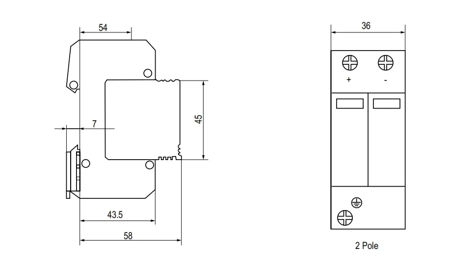
| Size (mm) (W × H × L) | W | 36 | 54 |
| H | 90 | 90 | |
| L | 67.6 | 67.6 | |
| Weight (kg) | 0.24 | 0.36 | |
Wiring Diagram
The wiring diagram shows the DC surge protector connections alongside the MCB, fuse and protective earth. The installation image below illustrates a 600V STD-40-PV inside a PV combiner box; confirm the final wiring against the instructions for the selected model.
Dimensions
Use the 2-pole SPD dimension drawing to check enclosure clearance and DIN rail space before installation; dimensions are shown in millimetres.
Drawing
Compare the illustrated 2-pole PV connection arrangements for grounded and ungrounded DC circuits when reviewing the system layout with your installer.