
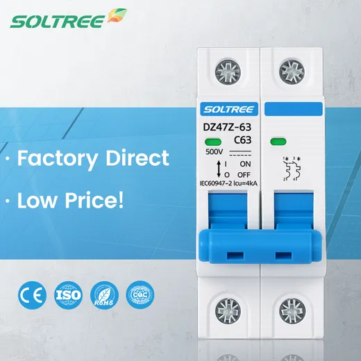
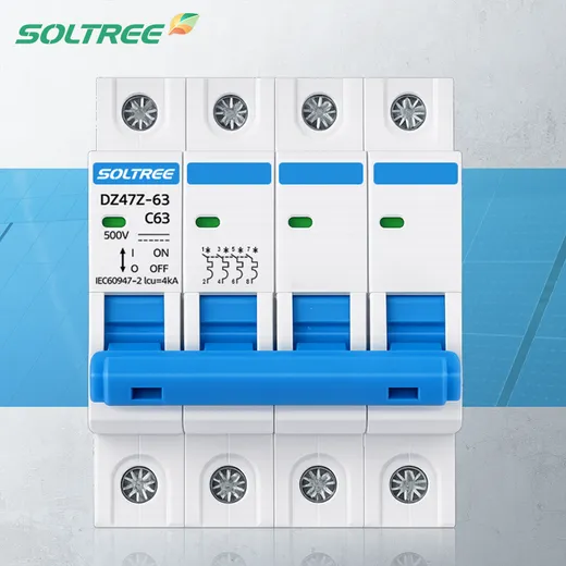
Solar PV circuits
Review compatible DC protection for combiner and inverter-side circuits. Share the string layout, inverter data and required protection arrangement.
Solar PV & DC circuit protection
Compare Soltree 1P–4P DC MCB models for compatible PV and DC distribution circuits. Review the voltage rating, fault level and wiring arrangement together, then request the configuration and documentation your project needs.
Understand the circuit
A miniature circuit breaker provides overload and short-circuit protection within its specified operating limits. For a DC project, the selected device must be rated for the system voltage and fault conditions, with the pole arrangement and connections confirmed against its wiring diagram. Similar appearance does not make AC and DC ratings interchangeable.
Use the maximum voltage under the design conditions, not just a nominal system label.
Check the breaking rating at the applicable DC voltage against the prospective fault current.
Confirm polarity, earthing, protected poles and any permitted series connections from the model documentation.
Product range
Compare the published models below. Open a product page for its listed specifications, and include the exact model in your enquiry.
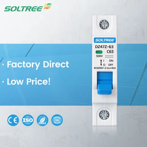
MCB-DC-1P
View specifications
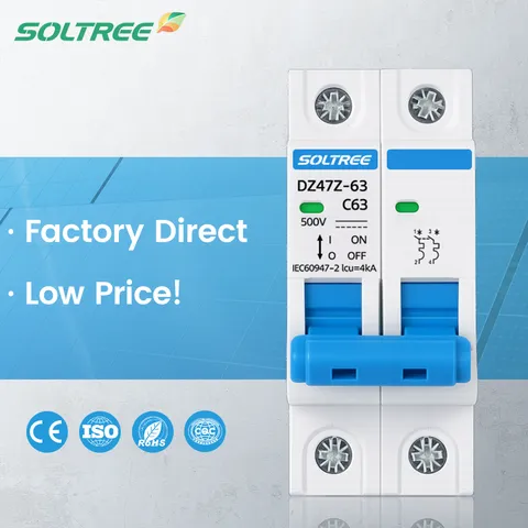
MCB-DC-2P
View specifications
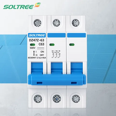
MCB-DC-3P
View specifications
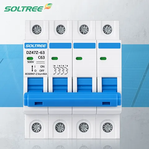
MCB-DC-4P
View specifications
Ratings & selection
These values follow the current product records. Pole count alone does not establish a different voltage rating or a permitted wiring arrangement; confirm the selected configuration and supporting documentation before ordering.
| Model | Poles | Rated voltage | Rated current | Breaking capacity | Trip curve |
|---|---|---|---|---|---|
| MCB-DC-1P | 1P | 500V DC | 6A, 10A, 16A, 20A, 25A, 32A, 40A, 50A, 63A (DC) | 6 kA DC | C (DC) |
| MCB-DC-2P | 2P | 500V DC | 6A, 10A, 16A, 20A, 25A, 32A, 40A, 50A, 63A (DC) | 6 kA DC | C (DC) |
| MCB-DC-3P | 3P | 500V DC | 6A, 10A, 16A, 20A, 25A, 32A, 40A, 50A, 63A (DC) | 6 kA DC | C (DC) |
| MCB-DC-4P | 4P | 500V DC | 6A, 10A, 16A, 20A, 25A, 32A, 40A, 50A, 63A (DC) | 6 kA DC | C (DC) |
STEP 1
Identify the application, maximum operating voltage and earthing arrangement. For PV, include the maximum string open-circuit voltage under the site design conditions.
STEP 2
Review circuit current, conductor capacity and prospective short-circuit current. Check the selected breaking rating at the actual DC voltage; a current rating alone is not enough.
STEP 3
Use the model wiring diagram to confirm connections and any polarity restrictions. If isolation is required, confirm that function explicitly in the device documentation.
Application planning
Review compatible DC protection for combiner and inverter-side circuits. Share the string layout, inverter data and required protection arrangement.
Compare the listed models for compatible DC supplies and equipment circuits. Confirm the operating voltage, load and expected fault level.
Battery systems can present demanding fault conditions. Provide battery and protection-system data so suitability can be assessed for the exact circuit.
For distributors & system builders
Discuss the product configuration and brand presentation together. Include your target ratings, models and quantities so available OEM options, documentation and order terms can be confirmed.
Provide the application, DC voltage, current, poles and required breaking capability, together with the circuit diagram.
Share the logo, label information, packaging artwork and destination market for your product range.
Confirm quantities and requested documentation, samples and delivery timing with your quotation.
Before you specify
Only use a breaker with an explicit DC rating suitable for the circuit. Some devices carry both AC and DC ratings, but their permitted voltage and wiring conditions can differ. An AC-only rating does not establish suitability for DC use.
Do not calculate a new voltage rating from pole count alone. Permitted pole connections, polarity and earthing conditions must follow the selected model documentation. The table above shows the values currently listed for each product.
Provide the maximum string open-circuit voltage under the design conditions, current information, inverter model and wiring diagram. Have the circuit designer confirm the voltage rating, fault interruption capability, pole arrangement and any required PV-specific protection.
Battery use requires a separate check of the system voltage, prospective fault current, breaker characteristics and wiring conditions. Do not assume that suitability for a PV circuit also establishes suitability for a battery circuit. Send the battery and system protection details for review.
An MCB provides overcurrent protection. A switch-disconnector serves a switching and isolation function. Whether a particular breaker is also suitable for isolation must be confirmed from its markings and documentation; the device name alone is not enough.
Send your application, target model or ratings, quantity and destination market. Include the wiring diagram, required documentation and any logo, label or packaging requirements. Configuration, available order options and lead time are confirmed with the quotation.
Get a DC MCB quote
Send your requirements or bill of materials. If the model is still undecided, include the available circuit information so the configuration can be reviewed.
Product selection & quotations
Tell us your product requirements. Our team will help you find the right solution.
We use cookies to improve your experience. By continuing to visit this site you agree to our use of cookies. Privacy Policy