DC Surge Protector
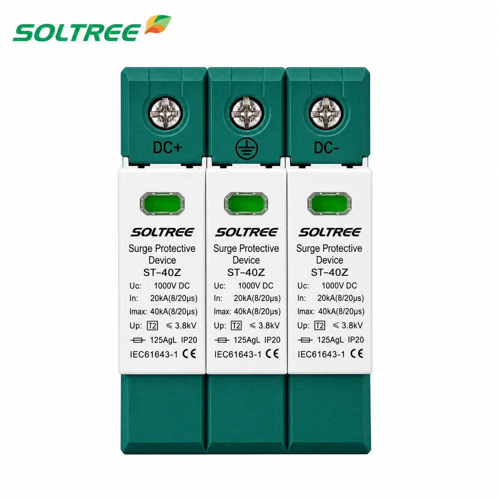
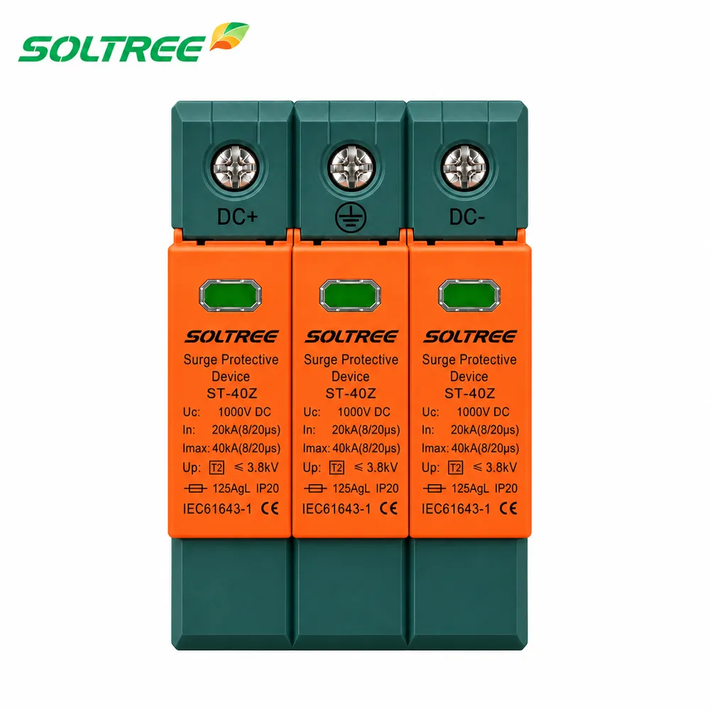
Type 2 1000V 3P DC Surge Protector SPD STD-40-PV
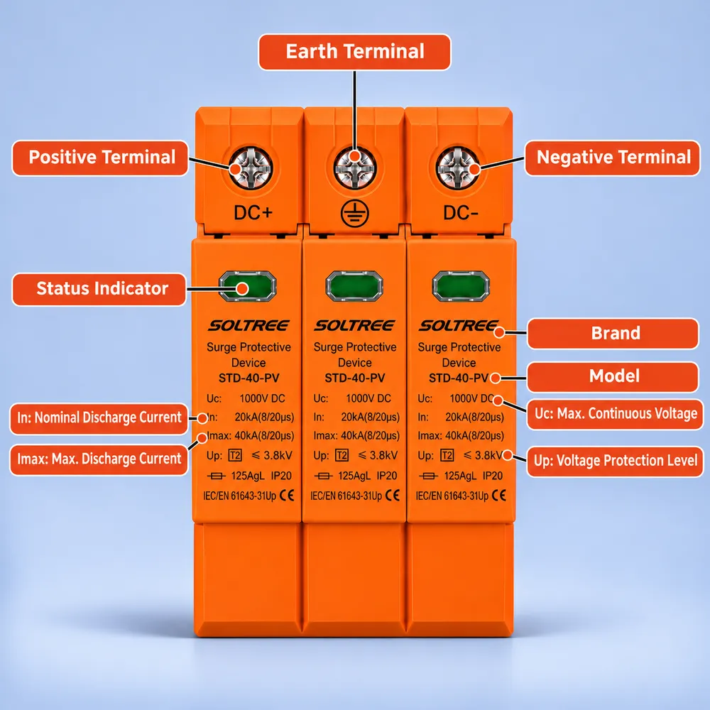
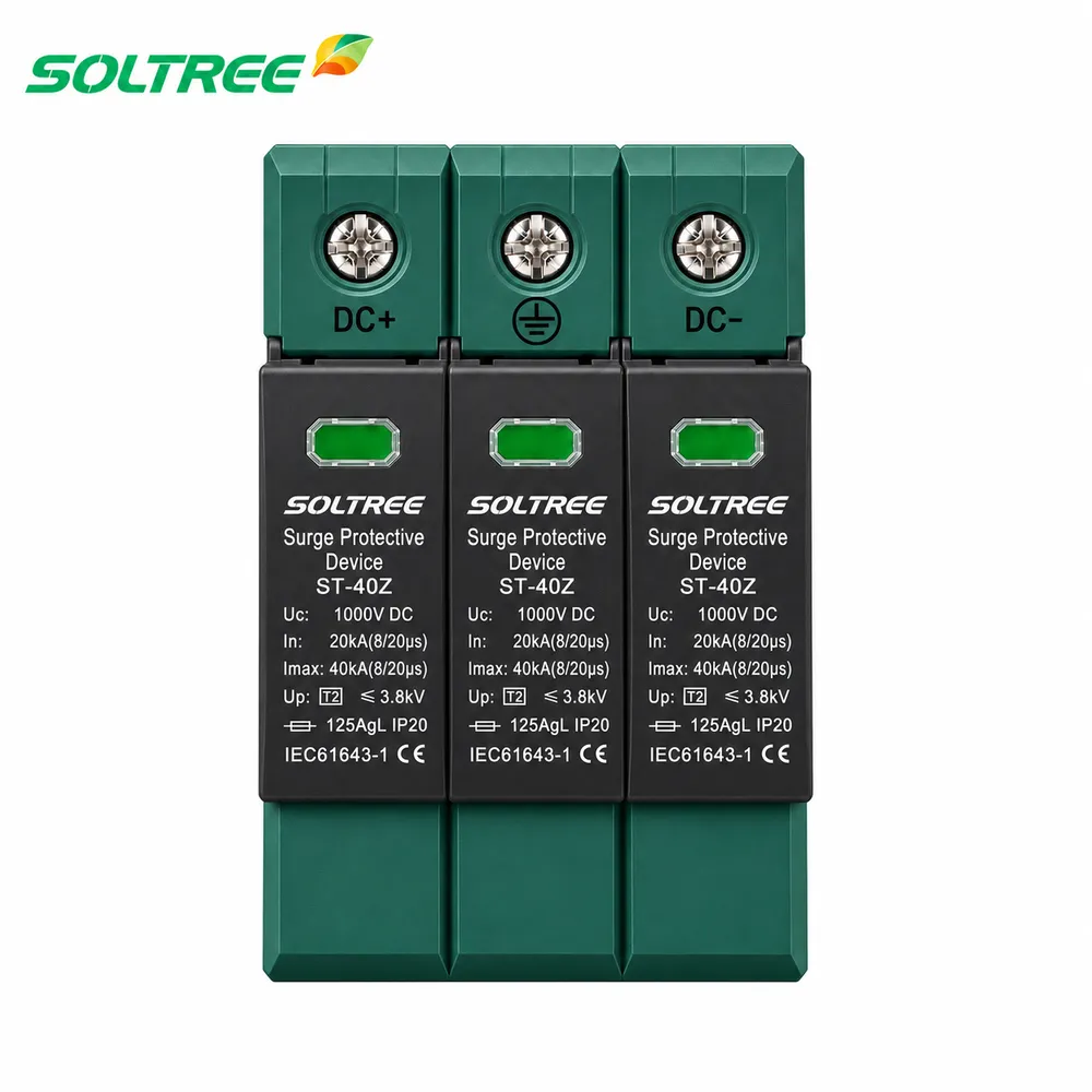
The STD-40-PV 1000V 3P is a Type 2 DC surge protector for PV combiner boxes and inverter DC inputs. It combines pluggable MOV modules, In 20kA / Imax 40kA surge ratings and a 54mm-wide three-pole housing. Review the 1000V specifications, terminal layout and dedicated 3P drawings below to plan your selection and enclosure layout.
Key Features
- Location of Use: String box, inverter
- Network Systems: (DC+)-PE, (DC-)-PE
- Surge Ratings: In = 20kA (8/20 μs), Imax = 40kA (8/20 μs)
- IEC/EN Category: Class II / Type 2
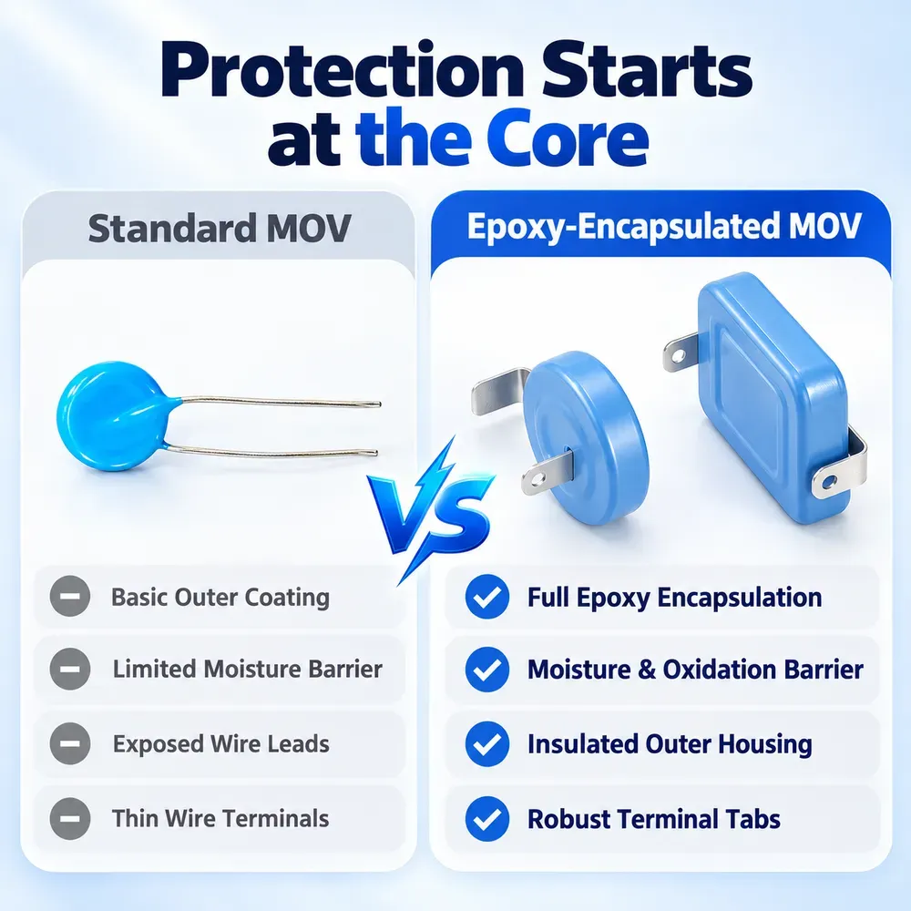
- Protective Elements: High Energy MOV
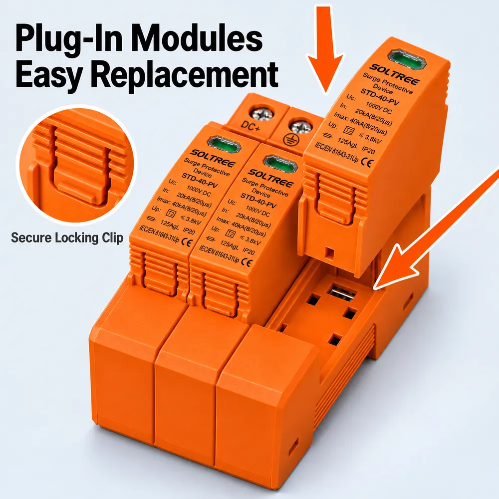
- Housing: Pluggable Design
- Compliance: IEC/EN 61643-31
Samples available · OEM pricing on request · Ships worldwide
Application
Choose the STD-40-PV 1000V 3P for PV projects that specify a Type 2 DC SPD with a three-pole connection arrangement. Typical installation points include string combiner boxes and the DC input side of solar inverters. The device uses high-energy MOV elements to limit transient overvoltages from induced lightning and switching surges; its nominal discharge current is 20kA and maximum discharge current is 40kA, rated with an 8/20 microsecond waveform.
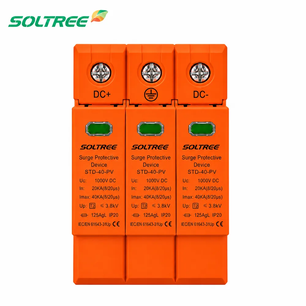
For selection, review the PV string voltage calculation, inverter requirements and earthing arrangement together. The 1000V rating must suit the maximum string open-circuit voltage under the project's site conditions. Use the dedicated 3P wiring diagrams to check the positive, negative and protective-earth connections against the marked terminals on the supplied unit. Three poles describe this DC device's configuration, not three AC phases or three independent PV strings.
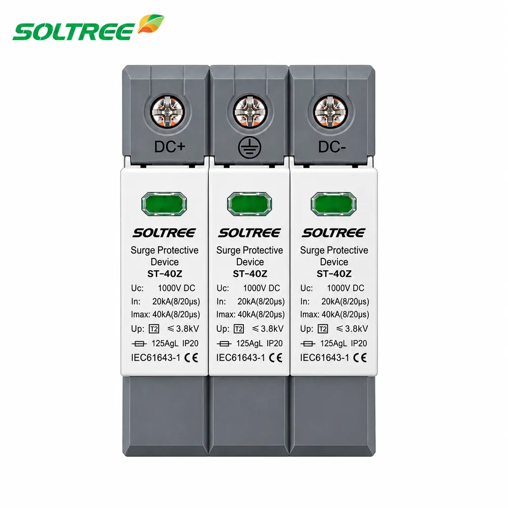
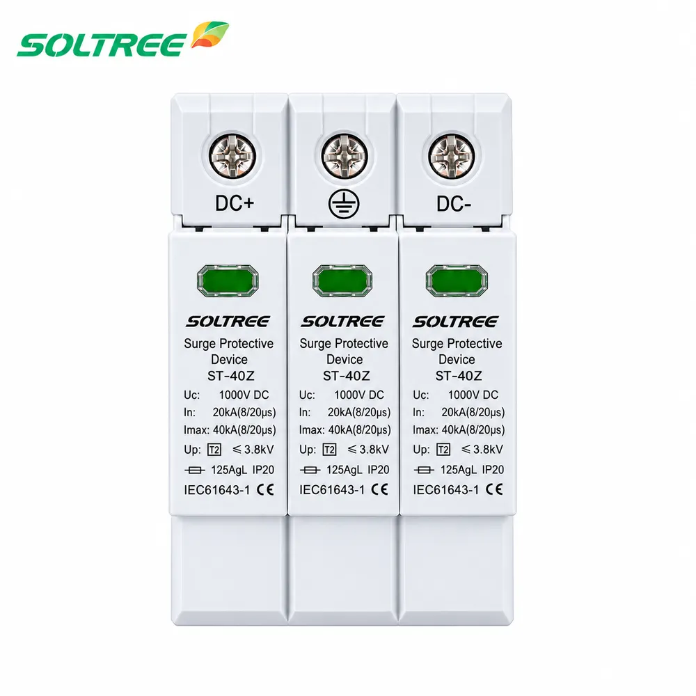
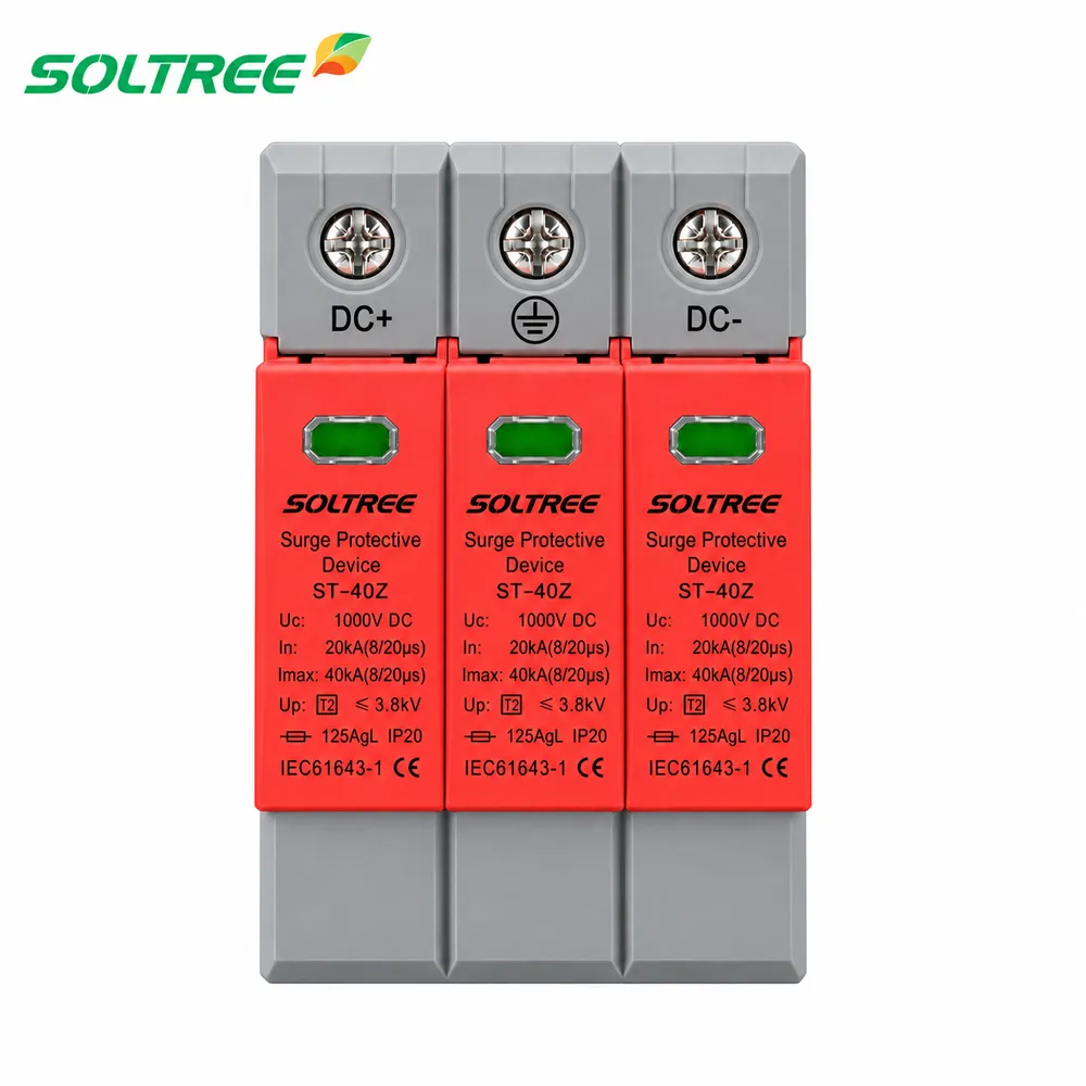
The 54mm-wide housing fits a DIN rail layout, while pluggable modules and visible status windows support inspection and replacement. Allow room for the conductors and access to the modules when laying out the enclosure. For a quotation, send the inverter model, string voltage calculation, wiring diagram, quantity and preferred housing color.
Specifications
Read the 1000V column for the model on this page: 3P, Class II / Type 2, In 20kA, Imax 40kA and a listed voltage protection level (Up) of 3.8kV. Ucpv is the maximum continuous PV operating voltage; Up describes the voltage protection level, not the normal operating voltage. The 1500V column is a separate series rating shown for comparison and does not extend the rating of the 1000V unit. Match the selected device to the PV circuit and the equipment protection requirements.
| Pole | 3P | 3P |
|---|---|---|
| Classified Test | Class II | Class II |
| Ucpv (VDC) | 1000 | 1500 |
| In (8/20)μs (kA) | 20 | 20 |
| Imax (8/20)μs (kA) | 40 | 40 |
| Up (kV) | 3.8 | 5.4 |
Remote Signal Contact
For projects with remote status monitoring, confirm whether the quoted 1000V 3P configuration includes a signal contact and request its terminal assignment and contact ratings. Check those details against the monitoring input before specifying the connection. The signal-contact information is separate from the SPD's PV power-circuit ratings.
| Maximum working voltage (V) | 250VAC/30VDC | 250VAC/30VDC |
|---|---|---|
| Maximum working current (A) · 1A (250V AC) | 1A (250V AC) | 1A (250V AC) |
| 1A (30V DC) | 1A (30V AC) | 1A (30V AC) |
Installation and Dimensions
Review the conductor capacity, stripping length, tightening torque and environmental limits below when planning the enclosure. The mounting information specifies H 35-7.5 / DIN35 rail. Use the dedicated 3P dimension drawing further down the page to check the three-pole footprint, and leave access to the terminal screws, status windows and removable modules. Confirm the final installation details against the instructions supplied with the selected unit.
| Wiring capacity (mm²) | Hard wire | 4~25 | 4~25 |
|---|---|---|---|
| Flexible wire | 4~16 | 4~16 | |
| Stripping length (mm) | 10 | 10 | |
| Terminal screw | M5 | M5 | |
| Torque (N·m) | Main circuit | 3.5 | 3.5 |
| Remote signal contact | 0.25 | 0.25 | |
| Protection class | All profile | IP40 | IP40 |
| Connection port | IP20 | IP20 | |
| Installation environment | No obvious shock and vibration | ||
| Altitude (m) | ≤2000 | ≤2000 | |
| Working temperature | -30°C ~ +70°C | -30°C ~ +70°C | |
| Relative humidity | 30%~90% | 30%~90% | |
| How to install | Installed with H 35-7.5/DIN35 steel mounting rail | ||
| Size (mm) (W × H × L) | W | 36 | 54 |
| H | 90 | 90 | |
| L | 67.6 | 67.6 | |
| Weight (kg) | 0.24 | 0.36 | |
Wiring Diagram
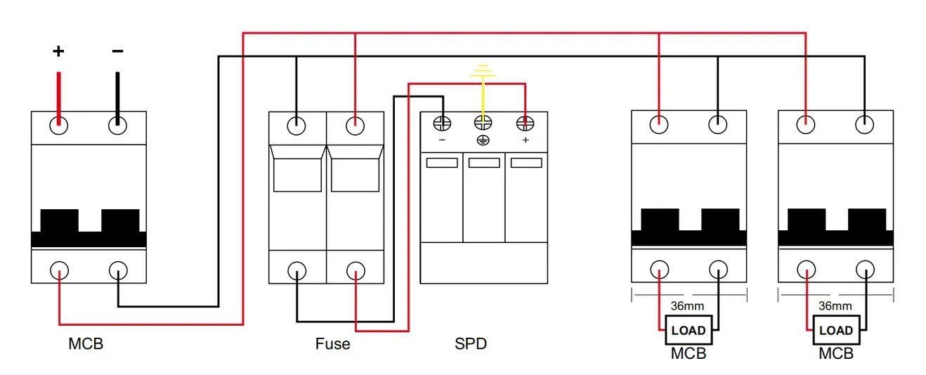
This 3P DC SPD wiring illustration shows the positive and negative conductors, an upstream MCB, fuse, protective-earth connection and downstream load circuits. Use it to identify the SPD branch and its relationship to the other DC components. Follow the polarity and earth markings on the supplied device when reviewing the connections; the diagram does not specify the MCB or fuse rating for your project.
Dimensions
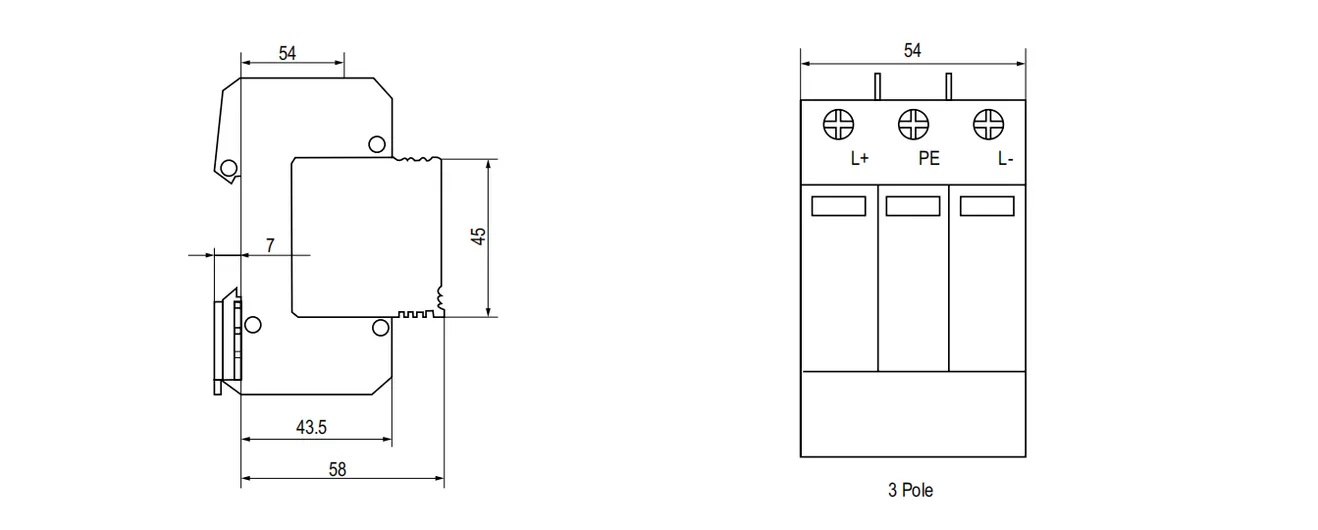
The drawing below shows the side profile and three-pole front view, with a 54mm front width and L+, PE and L- terminal positions. Dimensions are in millimetres. Use the complete profile to check DIN rail space and enclosure clearance, with additional room for conductor routing and module removal.
Drawing
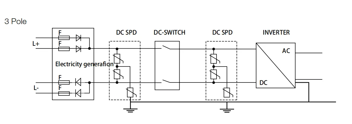
The 3 Pole system drawing places DC surge protection at the PV generation side and near the inverter, with a DC switch between the illustrated protection points. It shows how the SPD branches relate to the DC conductors and earth. Review the required protection locations against the actual cable route and site design; the drawing illustrates the arrangement rather than a fixed quantity of SPDs for every installation.